The Install
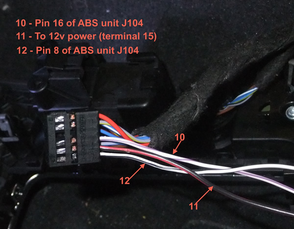
The wiring for the switch is as follows:
Pin 10 of switch goes to Pin 16 of ABS
Pin 11 goes to power
Pin 12 of switch with Pin 8 of ABS
Now your route is decided it's time to run your wiring. It's best to take the 2 wires going to the ABS controller and make an estimate in its length. Do a mock run to be as close as possible.
Then pull the wires back and wrap them up in tape before final install (friction preferred if you have it or can get it). You don't want unprotected wires running if you can avoid it. Leave a fair amount of extra length on each side and leave a good foot or two unwrapped so you can work with the wires and get a good final wrap with the tape. It may be easier to put the ABS pins on and leave your excess inside the cabin where it's easier to cut and work with. This way you can pre-wrap the wires all the from the ABS controller to the inside of the car.
To install the Power wire you have a few options. You can tap into the 12 volt plug and get power that way. Or if your like me you'll want to run a power wire to the fuse box.
Now the factory route is to take the power to red fuse holder at the back of the car. You can most certainly run the wire to it's original fuse block or you can run it to the a front Fuse Block if there is an open spot. Check the following fuse box, ST1 - Black ( 1st on the left of drivers side - 1st on the Right for RHD cars). If there is no open slots there check the black fuse block on the passenger side. The reason I specify those fuse blocks is because it is powered by the same main terminal as the rear connection (which is terminal 15). Now some people have just been tapping into the power on from the 12volt socket without issue. Not going to go to much into this as I prefer running my wiring as close to OEM as possible. However the tapping method would be much faster and cheaper and works.
If your going to the fuse block here is how you release the fuse block and insert a new line. Note, to save redoing pictures I will be reusing some to show how to install the new power line. SO keep in mind that you want the BLACK fuse block not the one shown.
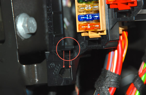
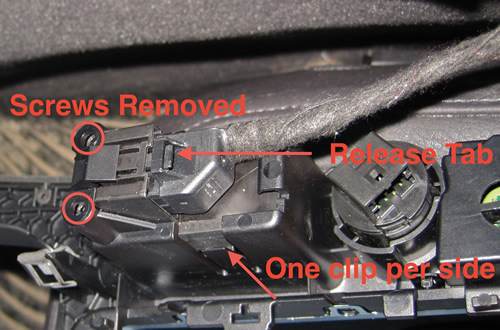
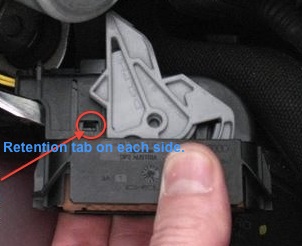
Step one: release the fuse block from the holder by pressing down on the tab shown. This will allow you to push the block back and remove it from the holder. You can see the fuse block already removed in this picture:
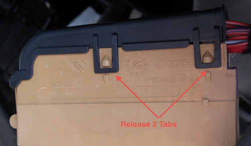
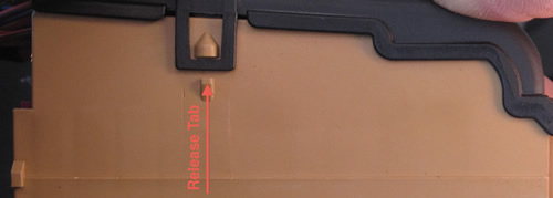
Next remove the cover from the back of the block There are 2 clips on one side and 1 on the other. once released the cover pivots open:
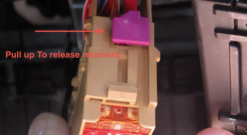
Now slide the pink retainer so you can insert your fuse into a slot:
Now slide your wire into a slot and reverse the procedure. Make sure you follow the same wire orientation as the rest of the wires in the fuse block just to make sure assembly goes smoothly. You will need a 5 amp fuse to complete the install.
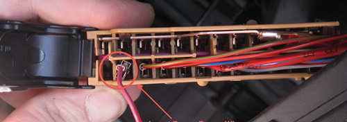
To give you an idea of the space you have to work with on the black fuse block, here is a picture of it after I inserted a wire:
Now we need to work on the plug for the switch.
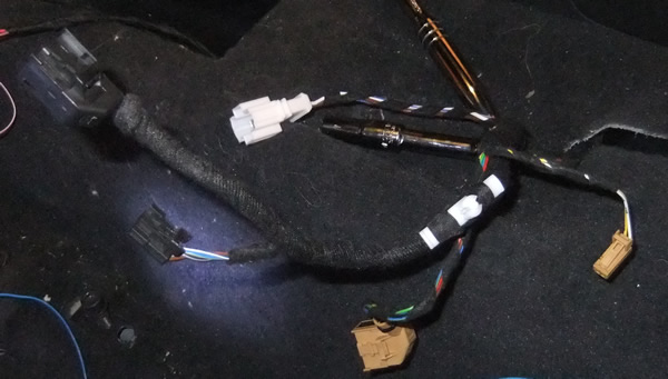
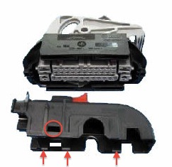
We will be working with the Black plug that you removed from the MMI panel earlier. Just in case you forgot which one that was:
In order to insert new pins into the plug the cover needs to be removed. There is a small slot on the side of the plug that has a release for the cover. Insert a small screwdriver or anything strong enough to lift the tab then slide the inside plug insert out.
Now we have the insert out we can do the wiring on the switch side. You will need to cut your wires in half that you sourced for the install. Wires 000 979 009 E are the ones used on this side. Cut them in half and join them to your extension wires running to the ABS unit.
Here is a picture of the plug with the wires inserted. Now your wires will be yellow if you got repair wires from Audi. If you read enough of my work you know I had a complete spare A4 harness that I rob for wires and parts which is why my colours are normally different in the write ups. .
Once you have the pins inserted you can put the connector back on and tape up any exposed wiring. My finished product (it helps to have the same type of tape as OEM:
You should mark one of the wires so you remember which is which. Don't forget to mark both sides, you'd be surprised how many mark one side and not the other.
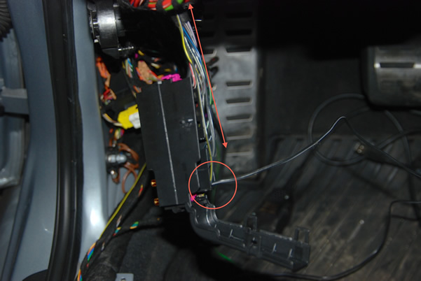
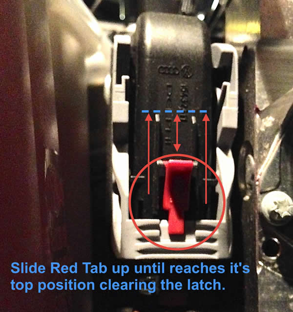
Taking the ABS plug apart is the real trick of the install. First you need to take the red lock shown and raise it up to release the grey lever (about 1/4").
Latch Unlocked:
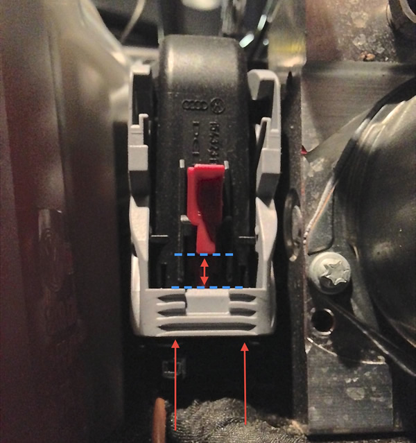
Then pull the grey lever upward to release the plug. They can be stiff so don't be afraid to apply a little bit of pressure. Of course double check if your having real issues, you don't want to break the plug by accident. Sometimes applying pressure to the plug while you raise the latch helps.
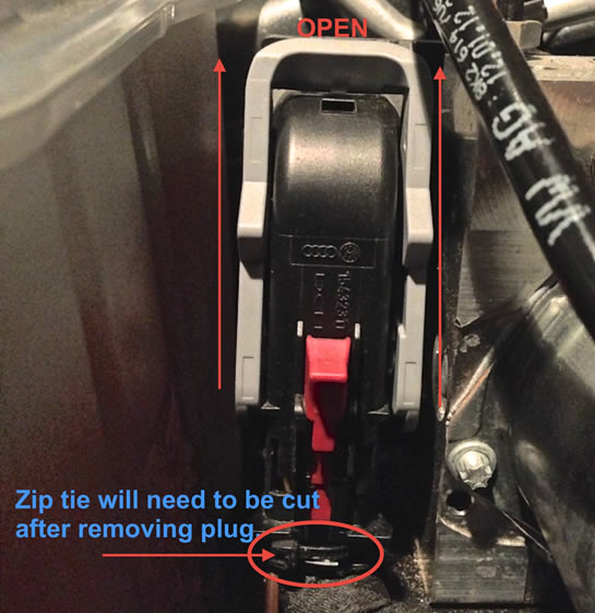
After the zip tie is removed it's time to get the black cap off of the plug. This will be one of the more difficult parts of the install.
There are clips on the side and front that have to be relieved before the lid will come off. I recommend the engine bay be warm before starting to give the plastic a bit more flexibility. Not a good idea to work with plastic when it's really cold. I've had to replace lots of plastic parts because of this.
You will need to insert a screw driver or something similar into the front slot and pry the front off of it's clips. You will then need to get the side clips released to pull the cap off. Here are a few pictures to try and help.
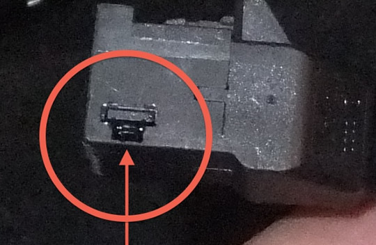
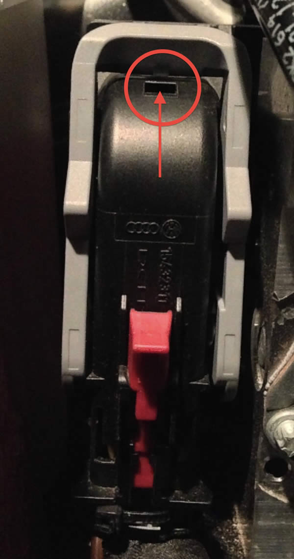
Although this is a small picture (enlarged) you can still just make out the tabs on the inside of the lid. You need to insert a small screwdriver or similar into the slot circled below on each side of the plug to get the tabs released.
Here is where you release the front/top tab:
Better picture of cap on
:
Once you get the cap off your on the home stretch. The nest step is to slide the Pink locks on the inside of the plug to their open positions. To do this move each one towards the out side as show in the next picture:
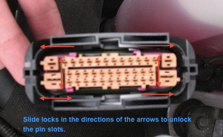
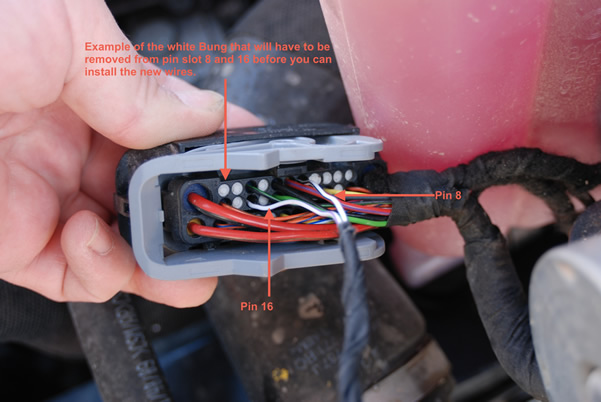
Once that is done you need to remove the two bungs (white things from first page) that are blocking the holes. The easiest way is to slide something up the pin holes and push them out. I have got them out from the top but it's not that easy. Try a sewing needle or find something stiff and long enough to fit the slot.
Once the white bungs are out you can insert your pins into the new slots. Hopefully you read through everything and remembered to put your new wire seals on the line before soldering and sealing it up.
Here is a picture from the top with the wires installed:
Once you have installed your wires it's time for coding. We'll take that to the last page.
Please note: AudiEnthusiast.com is in no way associated to Audi or VW in any way shape or form. All brand names and manufacturers listed here are for informational purposes only and are in no way endorsed by AudiEnthusiasts.com unless stated other wise.
WARNING!! All modifications and changes are done at your own risk. This site in no way approves the modifications performed here for your vehicle. Please check with your dealer before performing any changes as they may void portions of your factory warranty.