.:Hill Hold Assist
There will be some parts here you will need to work on your own and decide which route is the best for your application. I'll try and provide as much information as possible.
Install:
There are a total of 3 wires for the install. Doesn't sound like much but they are split between the engine compartment and interior of the car.
The 3 wires are 2- ABS unit and 1 power for the new switch function.
Before you begin the wiring you need decide how you want to get the wires to the ABS unit.
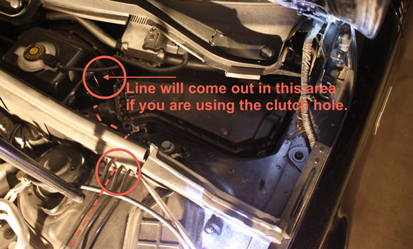
If your driving an Automatic car then you can use the hole in the firewall where the clutch would be. If you are the adventuress type and got yourself a standard transmission like I did you need to look at other options.
You can remove the cover the for ECU (engine module) and sneak your wires out that way or you can follow the factory route which is the ultimate but will add 1-2 hours to your install.
Regardless of the method your going to have to remove a few things. I'll show you the steps for the methods as best I can and let you decide which way your going.
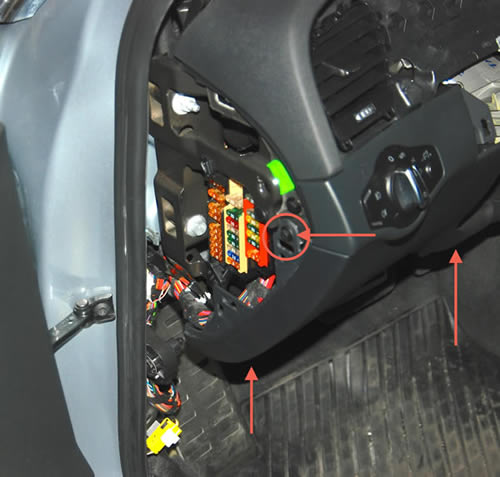
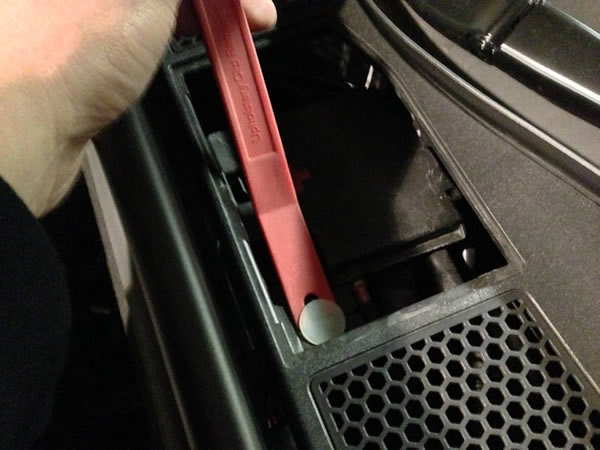
First step is to remove the lower panel from the dash. There are 3 bolts to remove, 1 behind the cover on the fuse panel and 2 on the bottom of the panel. Remove those then pull the panel out from it's clips:
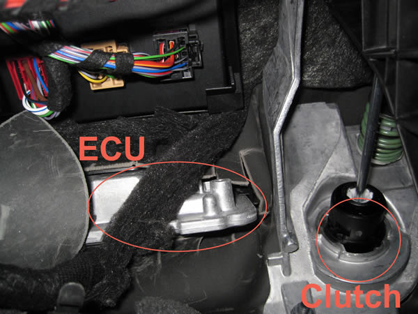
If you look at the rear firewall above the pedals you should be able to see the ECU. It actually comes from outside the vehicle and passes through the firewall into the cabin. In this picture you can see where the clutch is (covered hole for those with Automatics) and the ECU. The factory route is just behind that flap in the left of the picture.
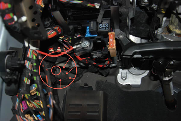
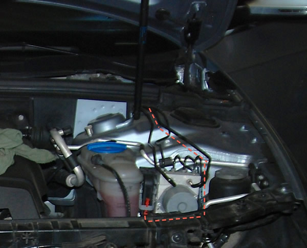
To the left (or right for RHD cars) you can see the round cut out of the firewall material and a harness going through the center of it. This is the factory harness going out into the engine compartment through the fender and wheel well. This is how I installed all my wiring for the front of the car. The cut out has a slit in it so you can remove it from around the harness to gain access to the entry point. If you wanted you could poke a hole through the rubber and take your wires out that way. Don't try to get wires through the same hole as the factory harness. Audi uses a thick tar like material to seal the wires in. You would most likely damage the factory harness and make a real mess trying to get through it.
It's not easy to see but in this picture you can make out the cutout and the harness going into the fender.
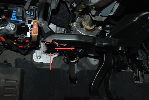
Although not completely clear here is where the opening is to go out through the clutch hole for automatic transmission cars. You can use a sharp hobby knife to cut a small slit in it to take the wires out. Like any of the options here I would tape your wire to something a little more rigid like a zip tie to make it easier to pass through.
Note, some pictures shown are from a RHD vehicle. The procedure is the same but some items may look out of place comparing it to a LHD vehicle. If there is significant differences I will inform you as part of the procedure.
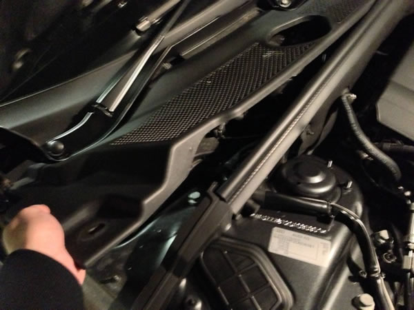
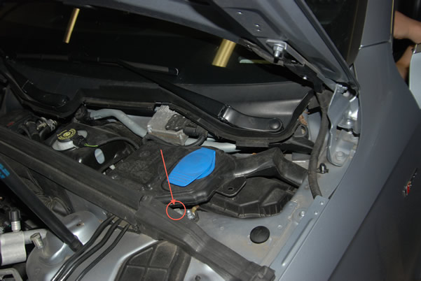
Now depending on your route your going to have a few different steps. One all share is removing the cover from the back of the engine compartment to gain access to entry points.
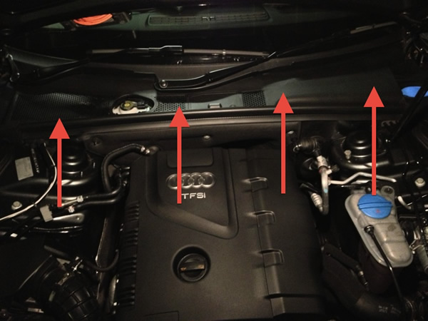
To remove the cover unscrew the 2 large plastic bolts and there is also one clip/plug situated where the booster point is.
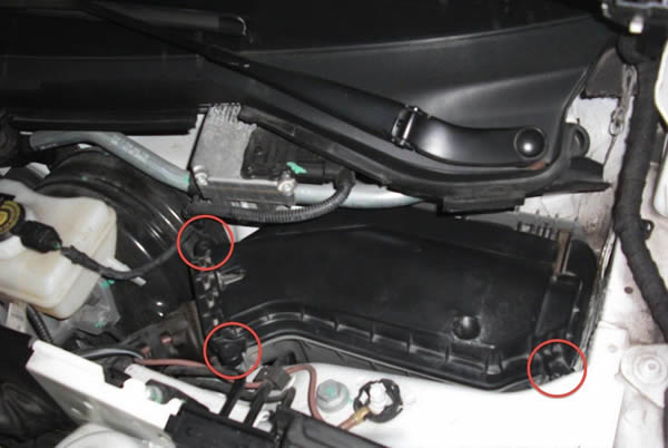
Step 1 remove the plastic bolt/caps from each side:
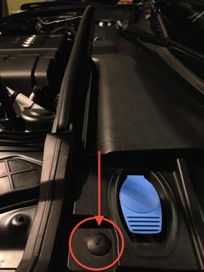
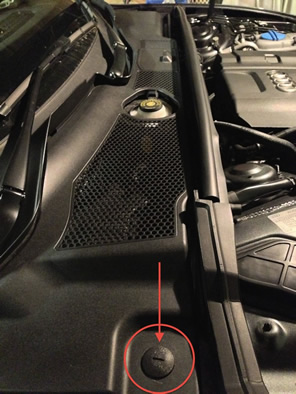
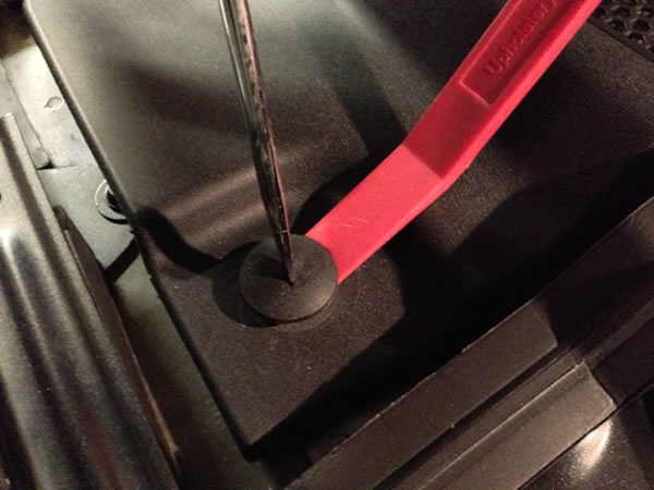
Sometimes the caps have a hard time being unscrewed. You can use a trim tool or a screwdriver to apply a bit of pressure to help, once they are raised up a little you can usually take them out by hand:
Remove the center booster cover and remove the clip shown. If you don't have a trim tool a pair of side cutter opened up works well to:
Lift the cover out to remove it:
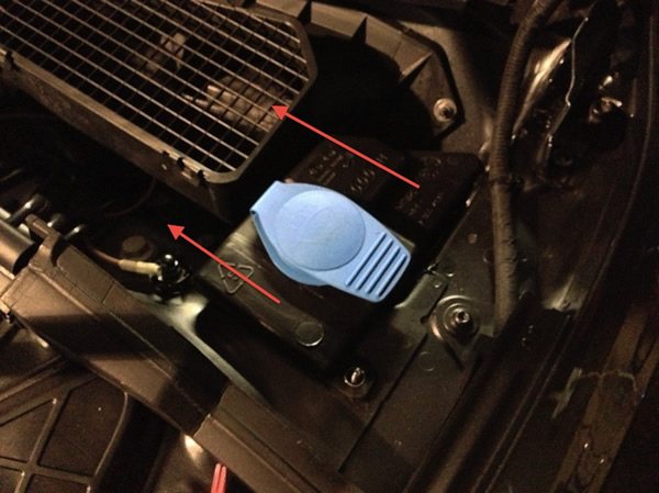
Once the cover is out remove the top of the washer fluid reservoir. The fluid goes down into a reservoir in the fender. Unless you just filled the fluid you should be able to remove the top part without getting wet. If it is full you can always use a Turkey Baster or coolant fluid checker to remove the fluid.
On RHD cars the washer neck appears to just pull out from the fender. On LHD cars it's larger and requires you to remove a 13MM bolt.
RHD (note you only need to do this on RHD cars if your running your wires on the passenger side factory route):
Just pull it out from the fender while lifting it over the fresh Air intake.
Removed:
LHD - Remove the 13mm bolt holding down the washer filler then pull the assembly away from the fender. The neck of the washer inlet goes right into the fender so be ready to pull out 4"-6":
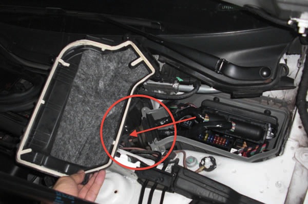
You now have access to the ECU holder and the entry point for the clutch hole.
If your going to use the ECU compartment for your routing, remove the 3 Torx screws (T30) holding on the LID.
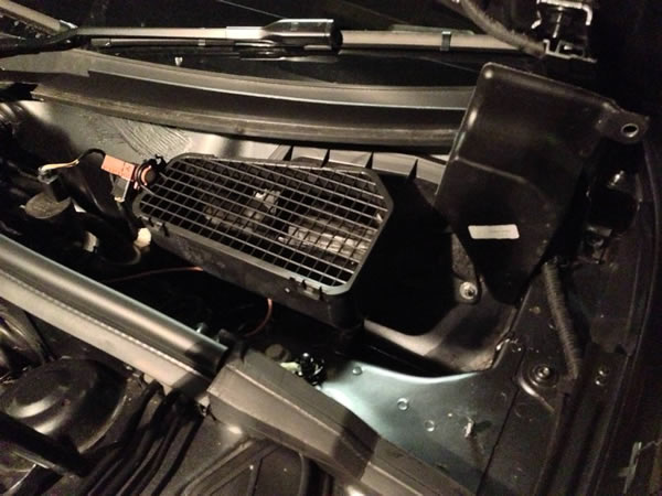
Now you can see what your working with.
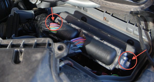
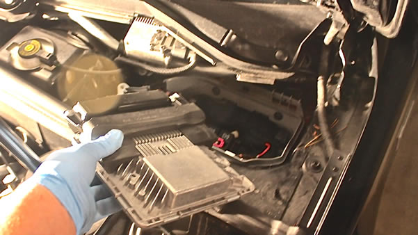
If you will need to remove the ECU for more room to work. This can be done without disconnecting the harnesses.
To slide the ECU forward you need to release the retention clip on each side. Do not use to much force or they will break (trust me it's not so easy replacing that bracket). To release the ecu just apply a bit of pressure to the clips and use the third hand you don't have to pull the ECU out. Easiest to pull one side up slightly and then do the other:
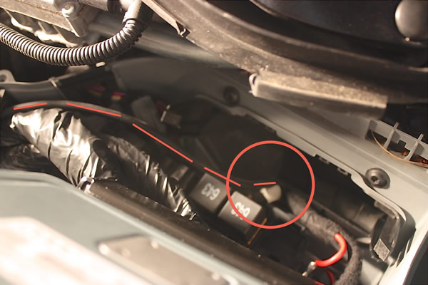
You will now have a clear hole into the car. There will be a grommet below the ECU bracket you can use to bring wires in and out of the cabin. Here is a few pictures from Ryan AKA phillips2024 on AZ and how he routed his boost gauge for his S4.
Removed ECU while maintaining the security bracket.
It's a bit dark but if you follow the line the hose goes in a grommet below the ECU opening with the wires for the relay and fuse block.
Here we can see how he got the boost line out of the ECU box and into the engine compartment:
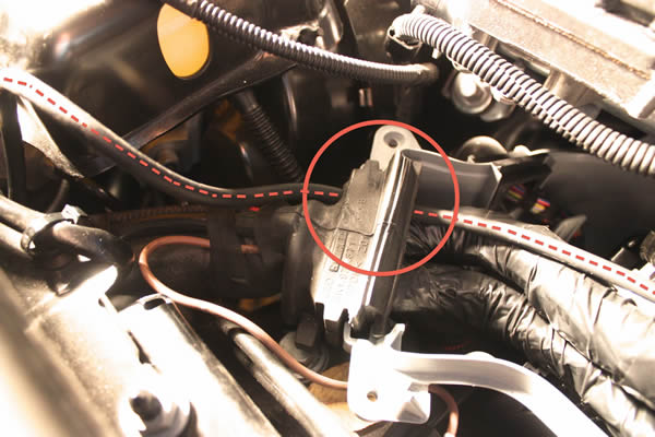
You can follow the brake lines through the rubber grommet that connects the two compartments.
If your going to follow the factory route (good for you) you have more work ahead of you.
Move onto page 3 for that information and pictures. Everyone else can skip to page 4.
Please note: AudiEnthusiast.com is in no way associated to Audi or VW in any way shape or form. All brand names and manufacturers listed here are for informational purposes only and are in no way endorsed by AudiEnthusiasts.com unless stated other wise.
WARNING!! All modifications and changes are done at your own risk. This site in no way approves the modifications performed here for your vehicle. Please check with your dealer before performing any changes as they may void portions of your factory warranty.